
Plasma Torch of the Automated Weld Overlay Machine
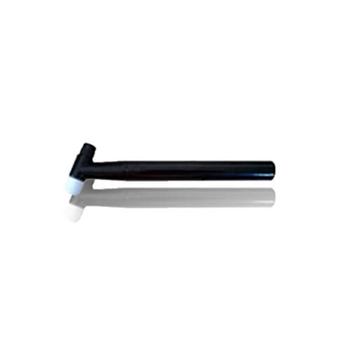
The plasma torch integrates water, electricity, gas, and powder supply systems. Through it, the plasma arc is generated and welding is completed, making it the core component of the welding process.
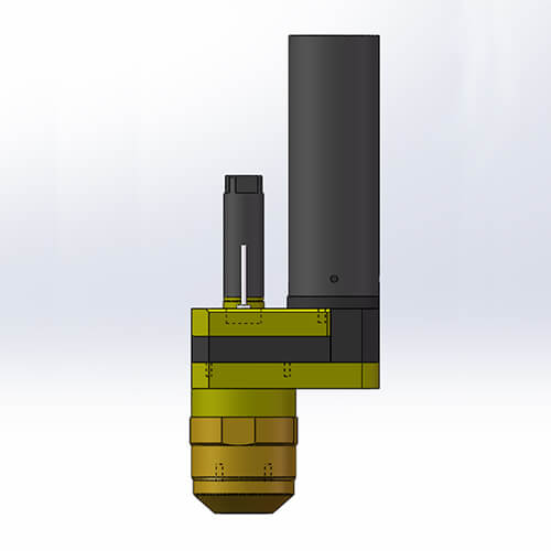
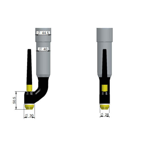
Plasma Torch Host Parameters.
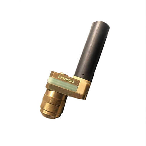
The Plasma Torch (also known as the Plasma Welding Gun) is the device responsible for generating the plasma arc. It incorporates water, electricity, gas, and powder supply mechanisms. This torch produces the plasma arc to melt powder materials and the base surface to complete the welding process, making it one of the core components of the entire plasma weld overlay system. Deewi Automation has independently developed its Plasma Torch, offering a range of specifications to choose from. Common specifications include: 500A, 300A, 160A, 100A, 80A, among others. Detailed parameters are as follows:
Structure drawing of Plasma Hardfacing Torch:
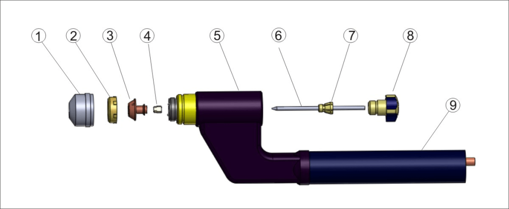
1. gas shield, 2. copper nozzle locking ring, 3. copper nozzle, 4. middle ring, 5. surfacing gun body, 6. tungsten electrode, 7. tungsten electrode clamp, 8. welding gun cap
Composition of the Plasma Torch:
The plasma torch assembly is typically divided into three components: the upper torch body, the lower torch body, and the insulating body. The upper torch body holds the tungsten electrode and has inlets for water and electrical connections. The lower torch body houses the nozzle assembly and connections for water, electricity, gas, and powder. The insulating body in between isolates and secures both the upper and lower torch bodies. The torch body is cast as a single piece, ensuring good sealing, durability, and safe usage. The quality of the nozzle is excellent, boasting a long lifespan and straightforward maintenance and replacement.
Plasma Torch Installation Precautions and Instructions:
Proper use and maintenance of the plasma torch are fundamental for its long-term stable and safe operation. When replacing the nozzle, sealing ring, center ring, or other components, it’s imperative to ensure the machine is turned off for safety reasons. During the replacement, the height of the welding torch should be above the water tank level to prevent cooling water from flowing into the powder delivery pipeline. When disassembling and assembling the tungsten electrode, ensure the welding machine arc is turned off. Before replacing the sealing ring, inspect it for any scratches or damages. Only install it into the sealing groove once you’ve confirmed it’s in new and flawless condition.
Maintenance and Usage Instructions for the Plasma Torch:
- Before use, inspect the equipment to ensure that the welding torch and connections for water, electricity, gas, and powder are correctly installed and securely fastened.
- When using the plasma weld overlay torch, ensure the cooling water is in circulation.
- The recommended welding angle for the plasma torch is between 80-110 degrees. If the angle is too wide, spatter will increase.
- Regularly clean the nozzle to prevent it from being clogged by powder.
Safety Precautions for the Plasma Torch:
- Before using the torch continuously, ensure it is adequately cooled. When the welding machine is not in operation, it should be set aside only after the power has been turned off for 10 minutes.
- Proper ventilation and fume extraction systems should be employed to eliminate the smoke produced during welding, and the emissions should comply with local environmental protection standards.
- Maintain a dry and tidy working environment. Lay insulating mats on the ground. Workers are required to wear protective clothing, welding helmets, and insulating gloves. Ensure that personnel and flammable materials stay away from flames and fumes. It’s strictly forbidden for workers to directly touch electrified or heated components.
Deewi Automation Technology Co.,Ltd.
We are glad to offer technical solutions to people who are interested in our products. You just need to fill a form.
Get in touch with us today!