The whole process of automobile panel mold using Laser Hardening Systems
Car coverings are related to the beauty of the car (appearance is the tangible value) and safety (safety is the first priority). They are an important part of the car, including the body, chassis, and engine cover. The cover part is stamped multiple times by a stamping die. The die itself will be partially worn after multiple stampings. At the same time, the worn die will also scratch the sheet metal parts. In order to prevent the die from becoming a “grinding tool”, it needs to be Local quenching and strengthening treatment is carried out in places where stress is concentrated. Traditional induction quenching and flame quenching, due to their strong dependence on personnel, complex operations, and variable mold surface shapes, lead to long quenching cycles, low quenching quality, cracking and other common problems. Large deformation after quenching requires secondary precision. Processing virtually increases the delivery cycle and processing cost of the mold. The use of a laser hardening system has significant advantages such as high quenching hardness, small deformation, and the ability to be repeatedly quenched.
1. Principle of laser hardening system
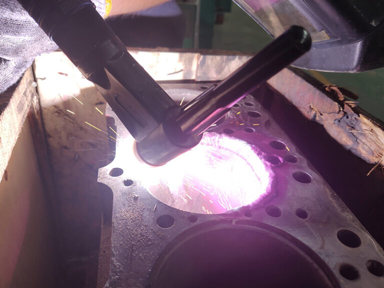
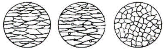
The laser hardening system uses laser surface quenching technology to target the defects such as low surface hardness, poor wear resistance, corrosion resistance, and fatigue resistance of mechanical parts. The metal material absorbs laser energy and the temperature rises to above the phase transformation point and below the melting point, and is transmitted through the matrix. Heat realizes self-cooling quenching, and solid-state phase transformation occurs within a limited depth on the surface of the component. Because the laser temperature is high and it heats quickly, and the laser is high-energy polymerized light, the mold dissipates heat quickly after being heated, so that the mold surface quickly martensitizes within 3 seconds (see Figure 1), the grains are small, and it is not easy to deform to achieve the purpose of quenching.
For steel materials, the surface of the material absorbs laser energy, and the surface temperature increases. Through thermal diffusion, a temperature gradient distribution is formed within a certain depth range. The temperature range is between AC1 and AC3. Pearlite Fe3C decomposes and C diffuses to form high carbon. Austenite, austenite is rapidly cooled to form martensite, and the final phase transformation structure is martensite, retained austenite, supersaturated solid solution or intermetallic compound, the organizational structure is fine, the surface hardness of the matrix, wear resistance, and Improved fatigue.
2. Automated laser quenching process plan
1). Laser hardening system components
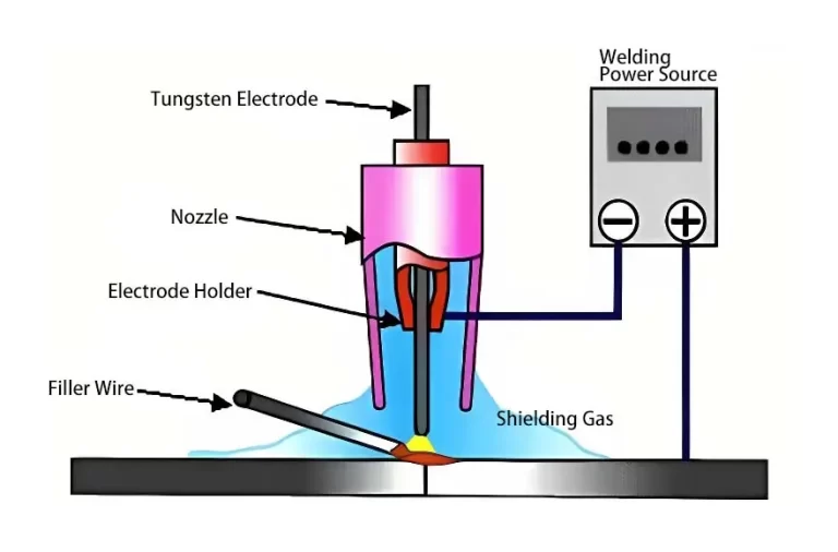
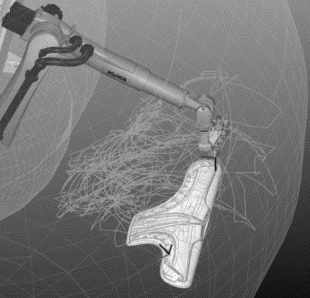
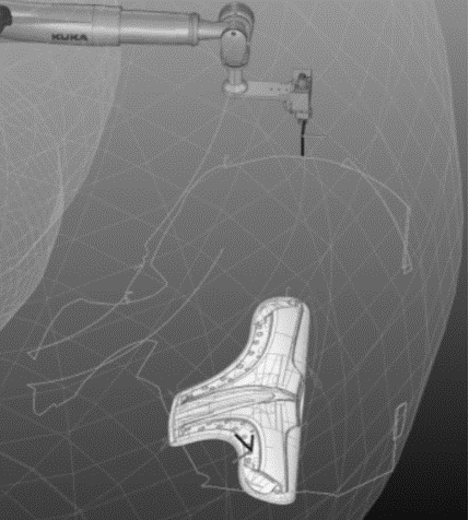
Laser hardening systems mainly include: lasers, robots, mobile worktables, etc. At present, fiber lasers are widely used. The laser converts the current into laser through the module, and then leads it to the quenching head through the optical fiber. The quenching head has a built-in integrating mirror for beam shaping, which integrates the laser into a strip-shaped uniform laser spot, which is emitted from the quenching head. ; Robots, commonly used six-axis robots, can realize special-shaped curved surfaces and multi-angle processing; the mobile worktable can expand the quenching area.2). Automated laser quenching process
When using the above equipment for quenching operations, the processing benchmark is determined in advance through CAD/CAM software, the processing path is compiled, the processing program is generated, and the program is imported into the control system of the laser hardening system, etc., so that the control system controls the equipment automatically according to the program. Quenching operation. First, use CAD/CAM software to find three positioning CH holes on the mold surface drawing, export the step format file, open it with Mastercam, measure the coordinates based on the three CH holes on the mold, and input the measured coordinate values into Mastercam. , set a good benchmark for the path line. Use Mastercam’s 5-axis path programming plug-in to prepare the quenching path line. The above are all common applications of existing computer-aided design and assisted manufacturing systems. In practical applications, you can also choose other CAD/CAM systems instead of being limited to the aforementioned ones. Several kinds.3). Selection of laser hardening system process
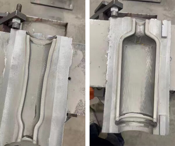
For the R convex angle of the drawing die, in order to facilitate polishing and eliminate the convex edges caused by polishing, corresponding quenching lenses (integrating mirrors) can be selected for quenching according to different sizes of R convex angles (see Figure 2). General experience: Use a 10mm integrator mirror for R convex angles with a radius less than or equal to 10mm; use a 20mm integrator mirror for R convex angles with a radius greater than R10mm and less than or equal to R50mm (where 10mm and 20mm refer to the rectangular light spot integrated by the integrator mirror) length).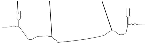
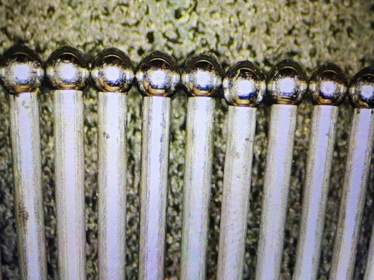
Through reasonable quenching path planning and grouping, R lobes, especially interfaces and small round holes, are effectively solved. These relatively short path lines are quenched to avoid problems such as laser collision and fiber winding, and fully automated quenching of R can be achieved. Lobe angle, as shown in Figure 5.

3. Comparison between laser quenching and traditional methods
1). Comparison of quenching quality
Three quenching methods, namely laser hardening system, induction quenching and flame quenching, were used to compare the hardness distribution of castings after quenching:- Laser hardening system: the hardness is more uniform, the quenching quality is more stable, the quenching surface is more beautiful, and the R-angle shape is better, which is beneficial to later research and matching.
- Induction quenching: The hardness is more uniform, the quenching quality is more stable, and the quenching surface is more beautiful. It is limited by the induction coil and has poor shape with the R corner. There are many induction areas (heat-affected zones) around the R corner, which is not conducive to later research and development.
- Flame quenching: uneven hardness, poor quenching quality (high and low hardness), poor quenching surface quality, better with R angle shape.
2). Comparison of hardened layers
Laser quenching and induction quenching are used respectively to perform slice analysis on the hardened layer:- Laser quenching: the depth of the hardened layer is about 1.1mm;
- Induction hardening: The depth of the hardened layer is about 3.5mm.